Team overview
Sizhe Ma: https://github.com/MaxMa6150

Sudong Wang: https://github.com/sudong-wang

Ying Xu: https://github.com/real-YingXu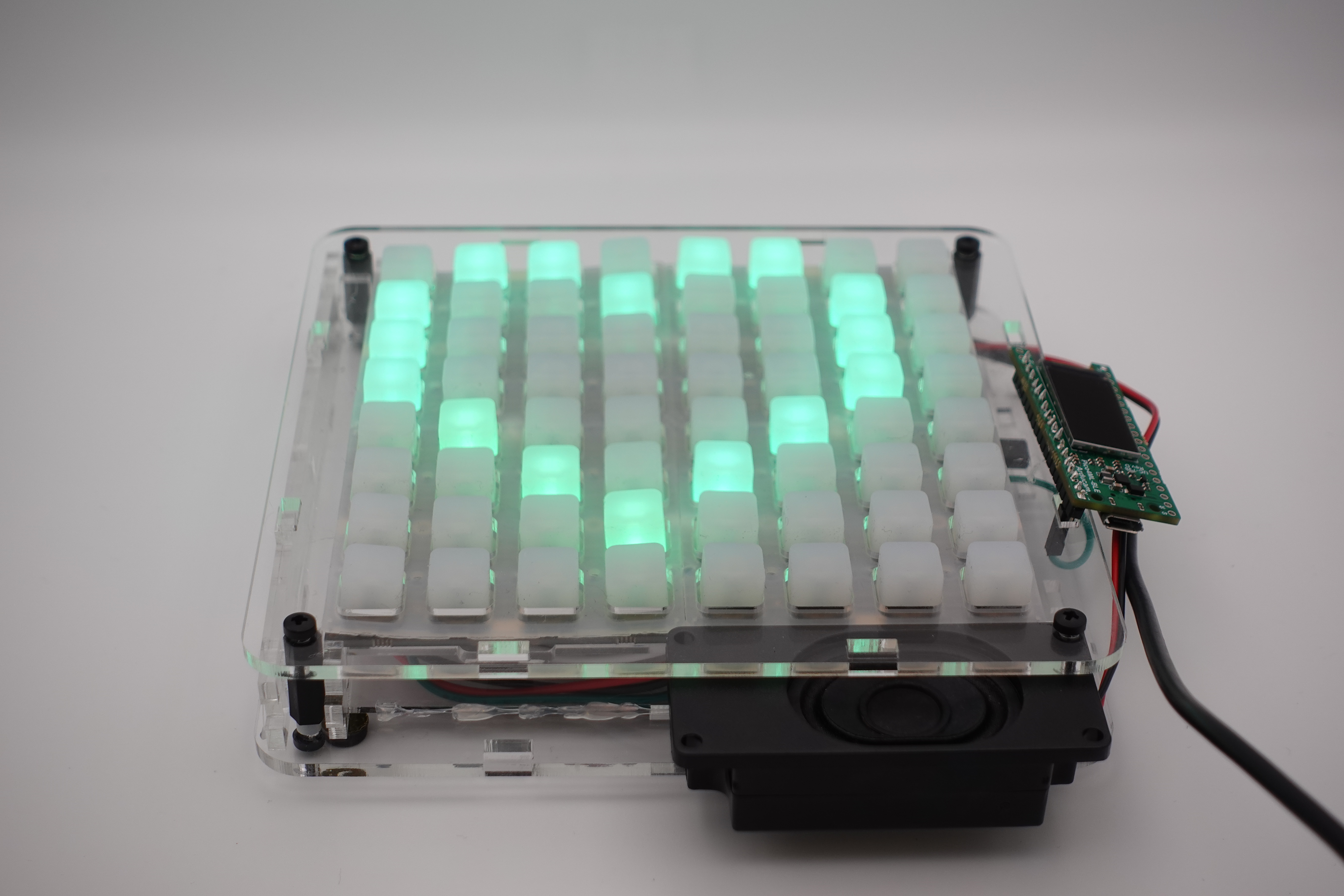
Project showcase
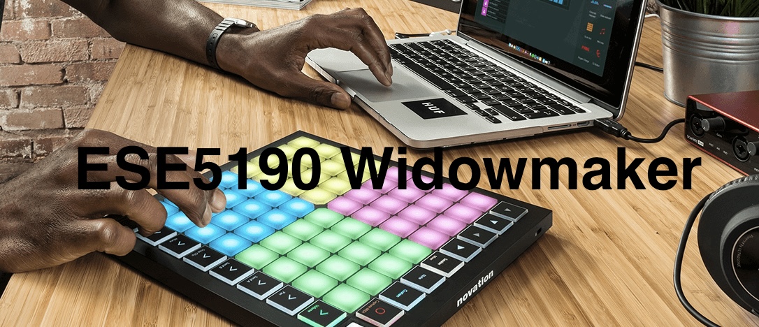
In this project,we made a launchpad with a sequencer that can loop drum beat. At starter, the launchpad will start with a black screen on the LCD display, then the four drum set will played along with the lcd display shows “launch” “pad” “music” “game” with the same color as the drum set color. Then the user will be asked to choose to play sequencer mode(1) or launchpad mode(2).
Lunchpad mode
When the user pressed the button in the right sequence, the music will play with the lights to play a full song with cool effects. Each 4 keys on the keypad represent the same music file. So if the users press the block in order, a whole song could be played by the speaker.
The demo of launchpad mode is shown in mode_launchpad.mp4 video file.
Sequencer mode
The user can proudce a 8 step drum beat with four drum sounds proceeding with the sample playing. The user can real time modify the drum beat by assemble different drum beat to the differet second of two period of 4/4 music intervel. When the pressed key(instrument) is played by the speaker, the LCD screen will refresh and show the current drum beat(‘o’ means no instrument is played, x means there is a playing instrument). By pressing the a yellow button in row 5, the sample will play in the fifth channel of the mixer along with the 8 step drumer.
The demo of Sequencer/Drum mode is shown in mode_sequencer.mp4 and sequencer_LCD.mp4 video files.
Project instruction
Component
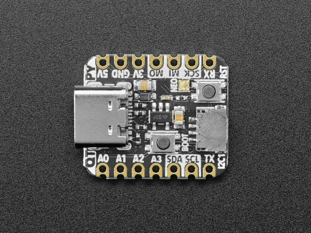
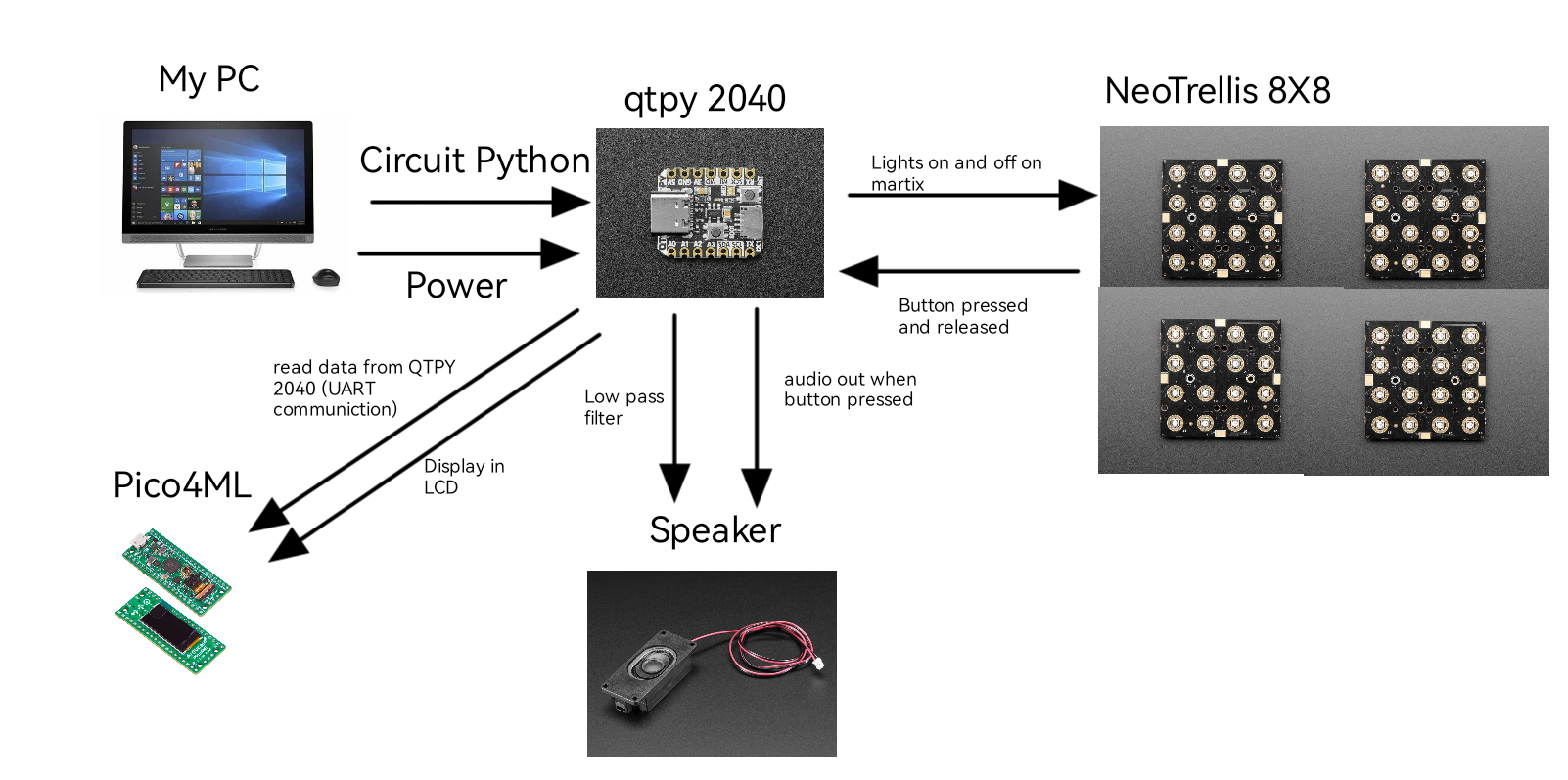
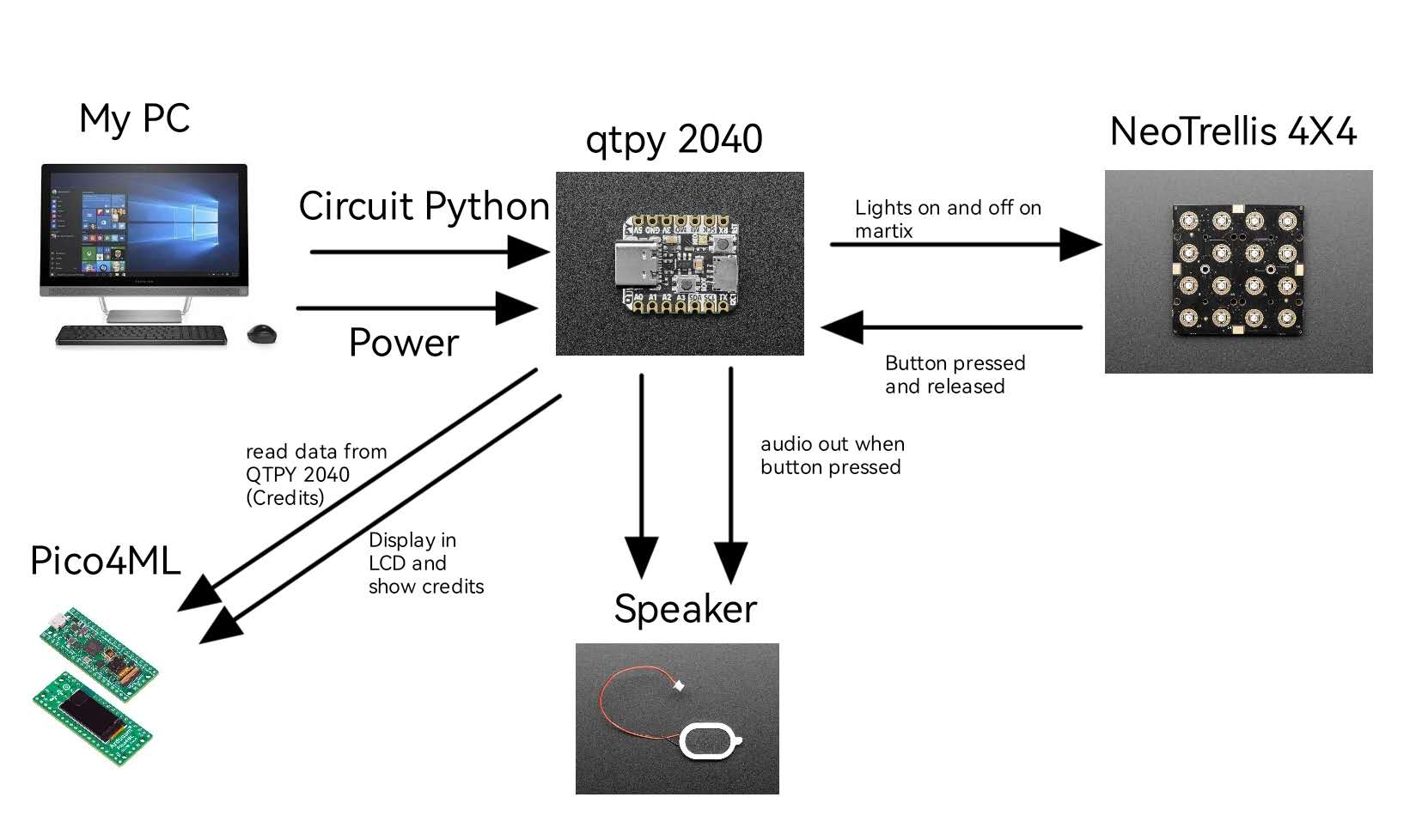
For this project, we mainly use four components: 1. QTPY 2040 for main controlling (controlling speaker, receiving users’ press/release feedback from Neotrellis, sending data to Pico4ML for LCD display)
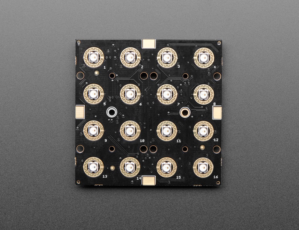
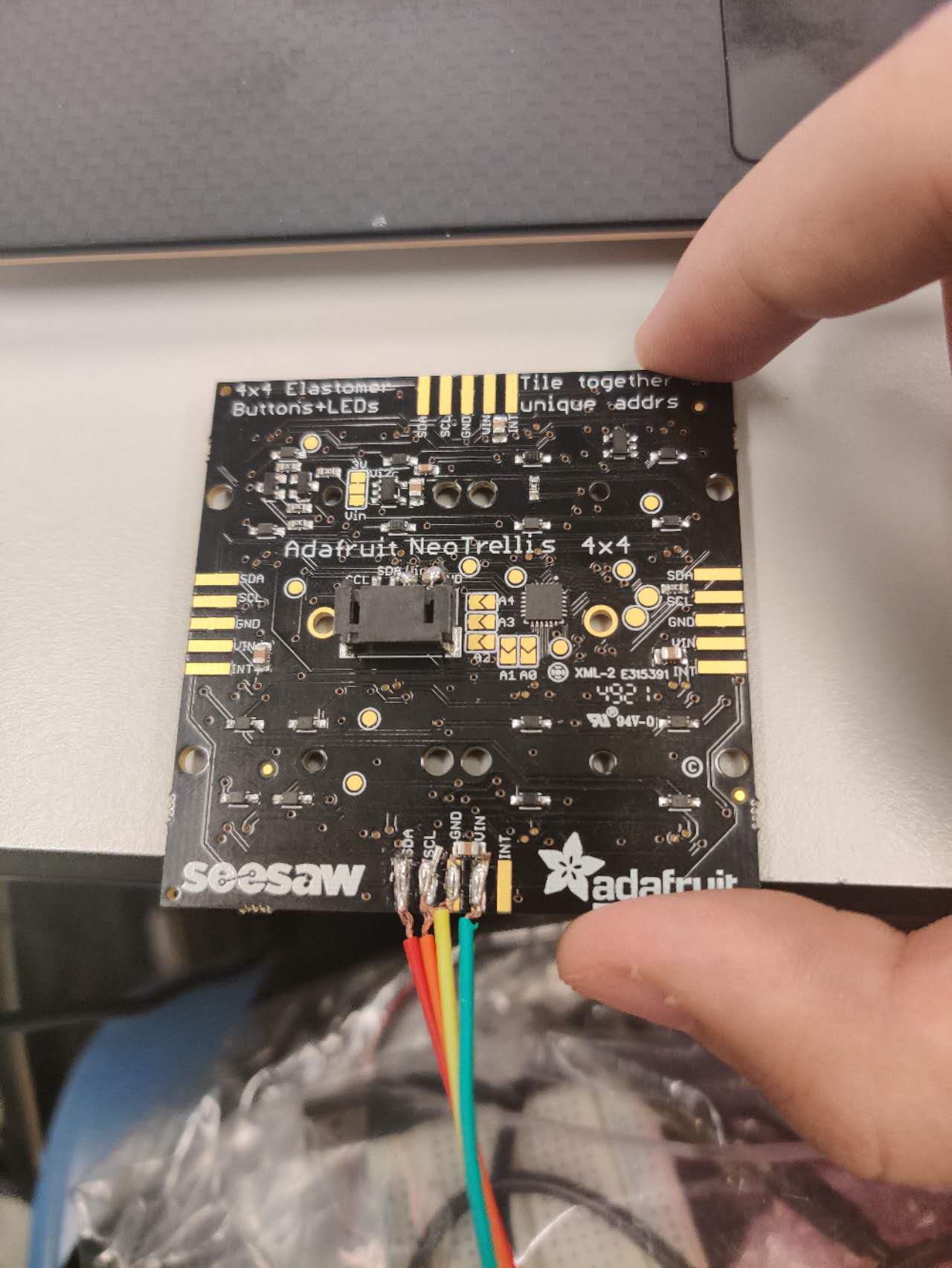
2. Neotrellis Keypad for user interaction
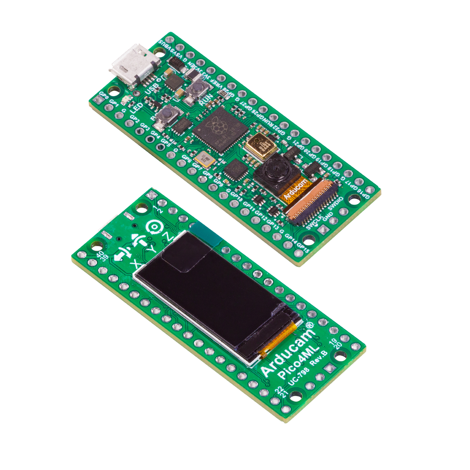
3. Pico4ML (communicating with QTPY 2040 with UART, receiving user feedback and displaying current stage on LCD)
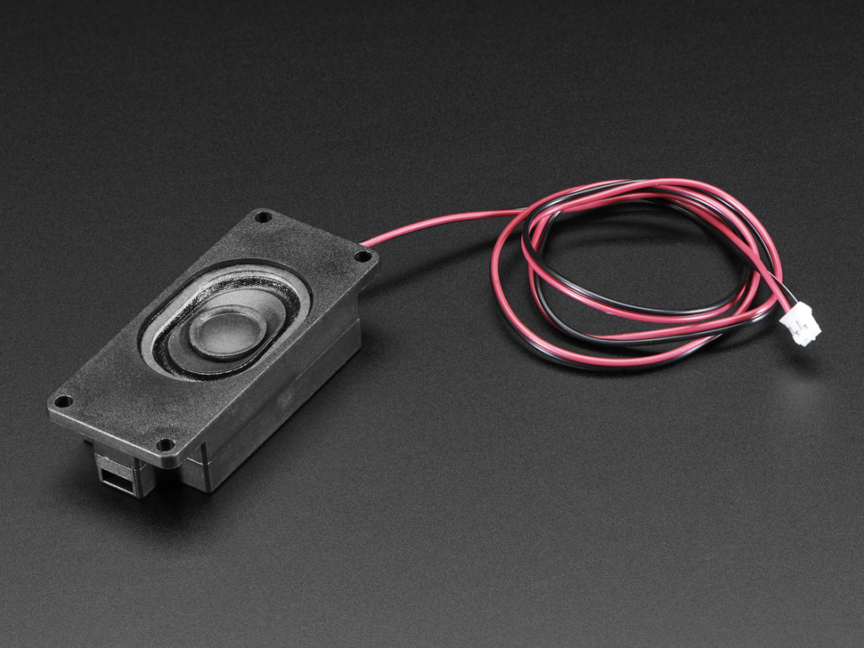
4. Speaker for .wav/.mps music playing
System diagram
be46a745f1526035cd1deeb1c4a80b3
Circuit Diagram/Building
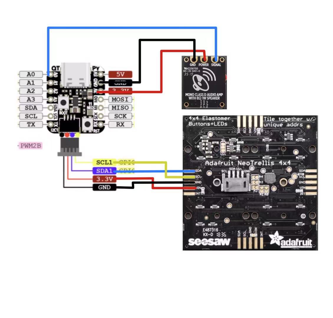
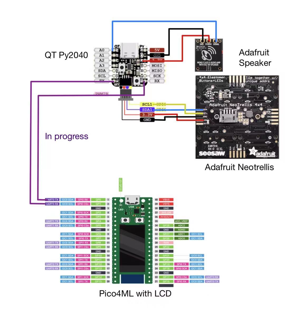
The circuit diagram:
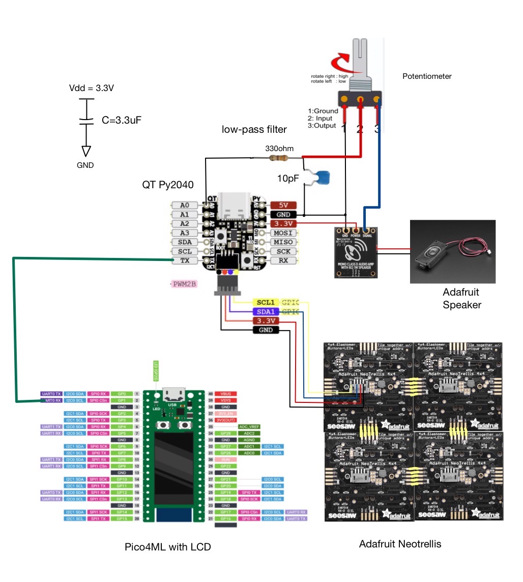
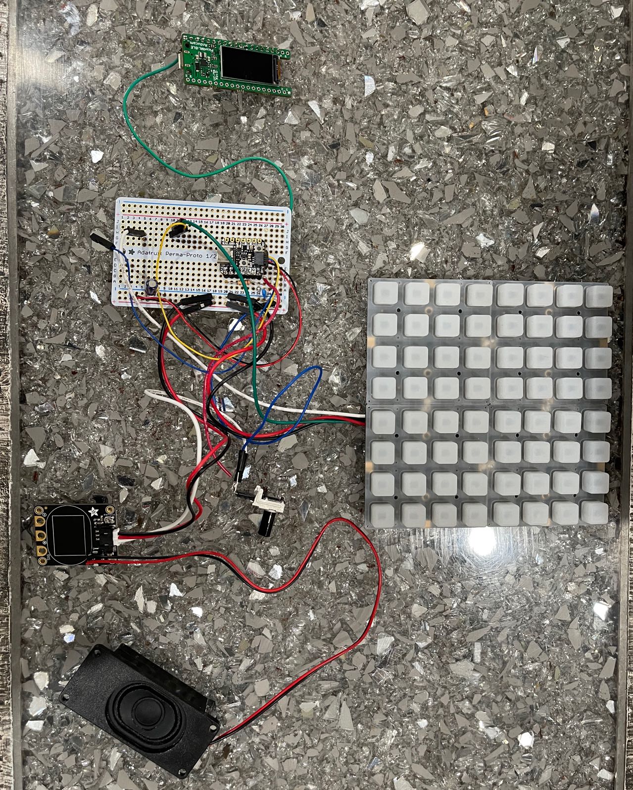
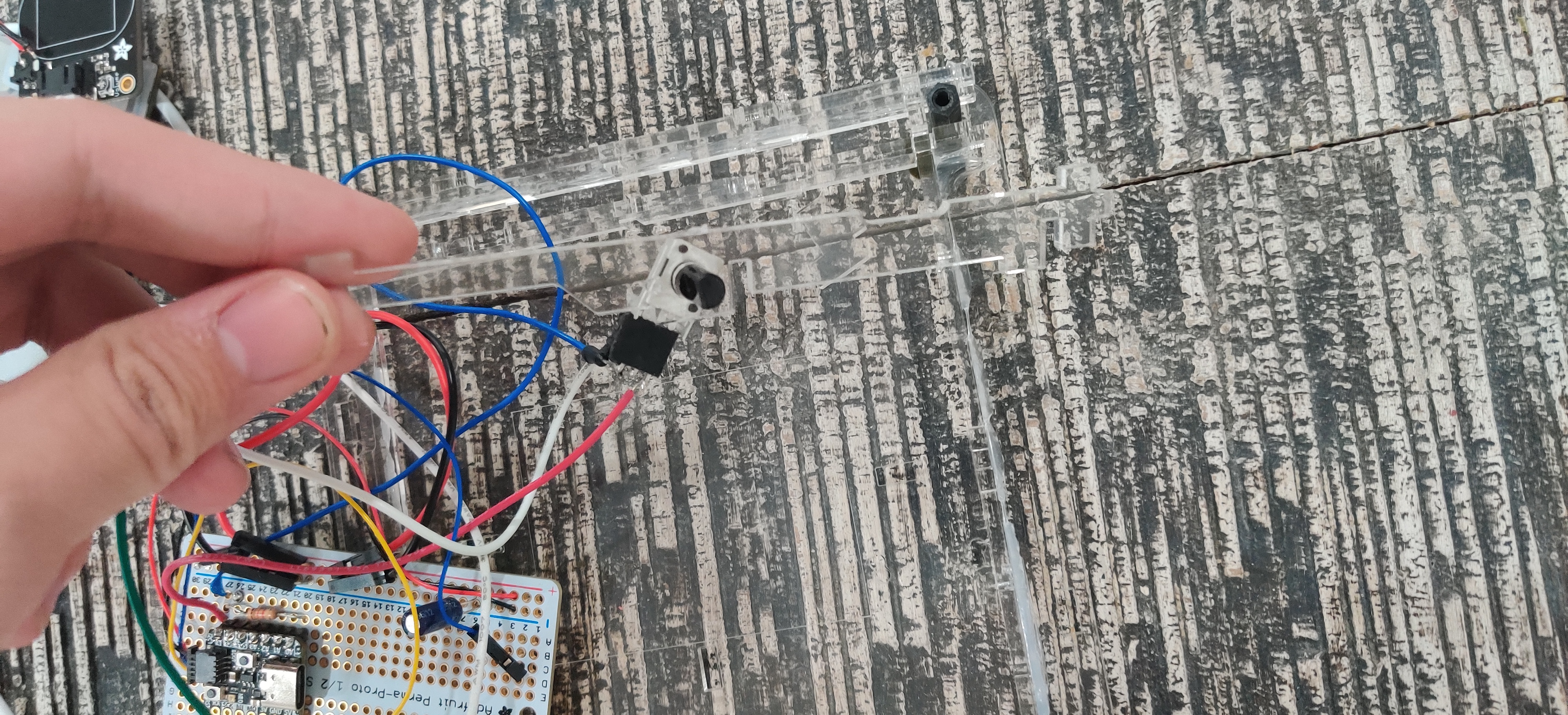
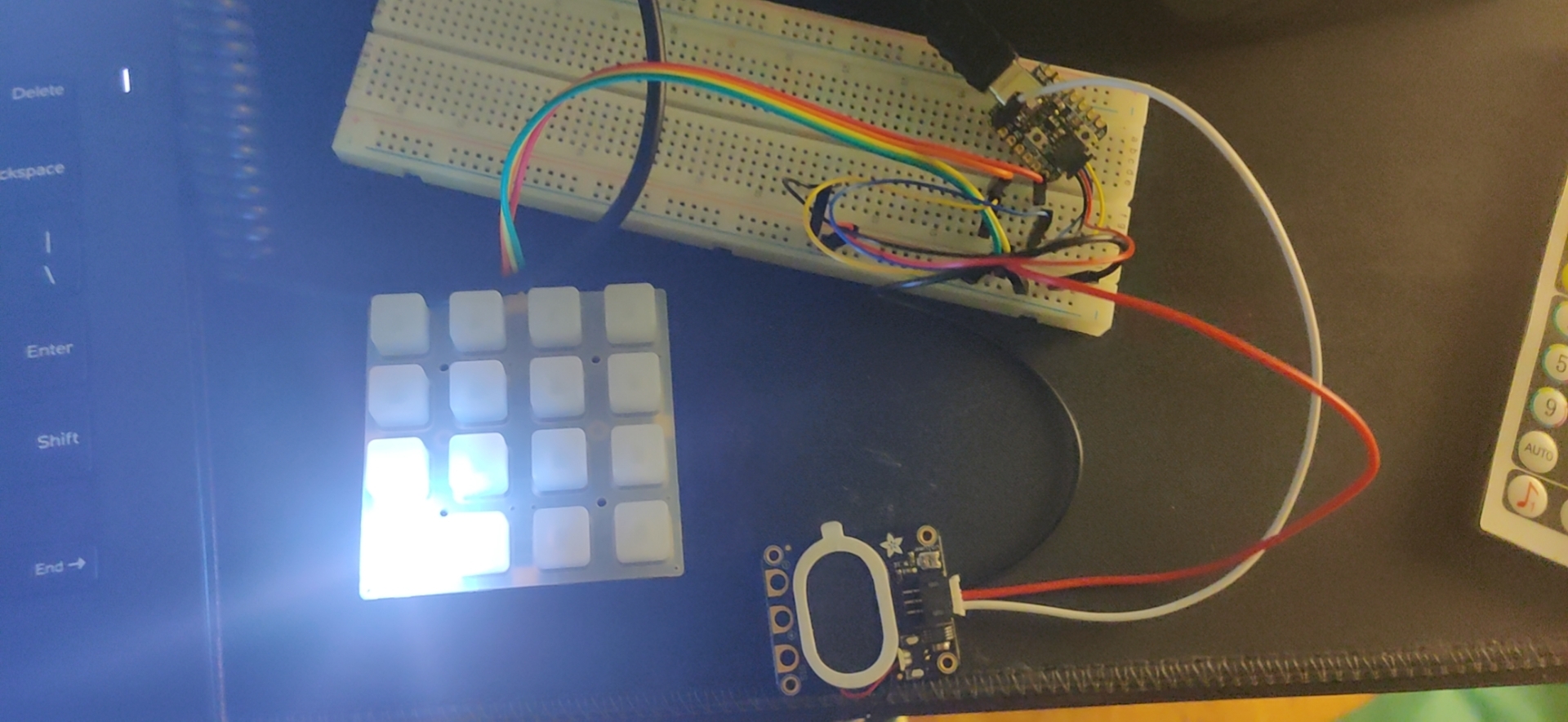
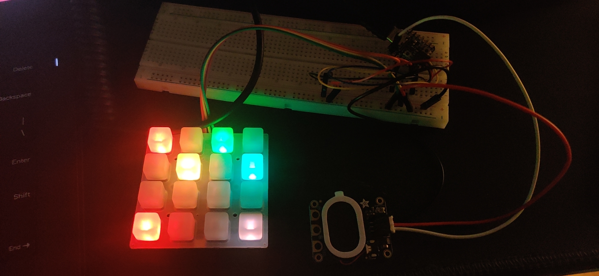
We firstly assembled all components, which includes Pico4ML, QTPY 2040, Stemma Speaker driver, 4 ohm 3W speaker, low-pass filter composed by 330 ohm resistor and 10pF capacitor, 3.3uF capacitor for short circuit protection, and variable resistor for volume controlling, on the breadboard and tested the functionality:
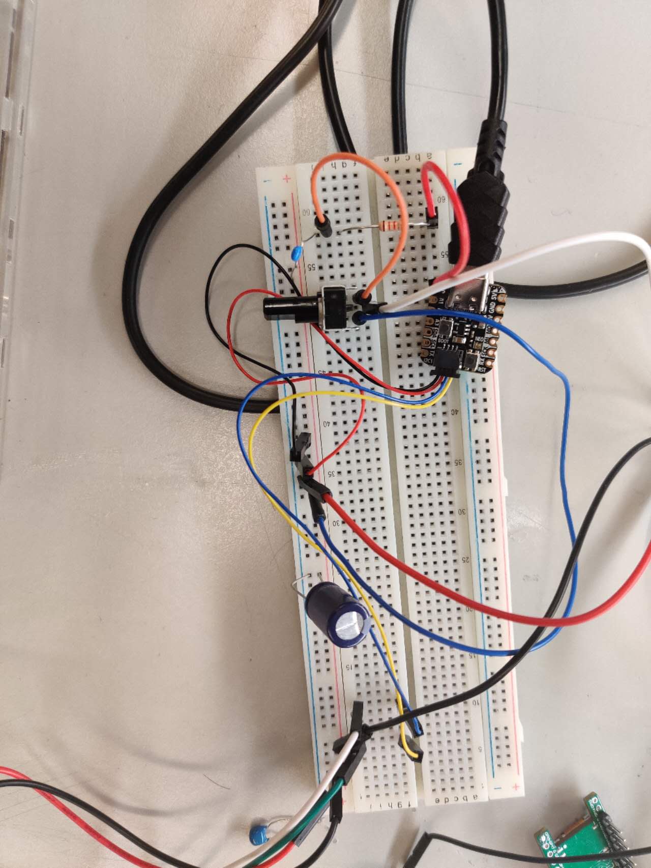
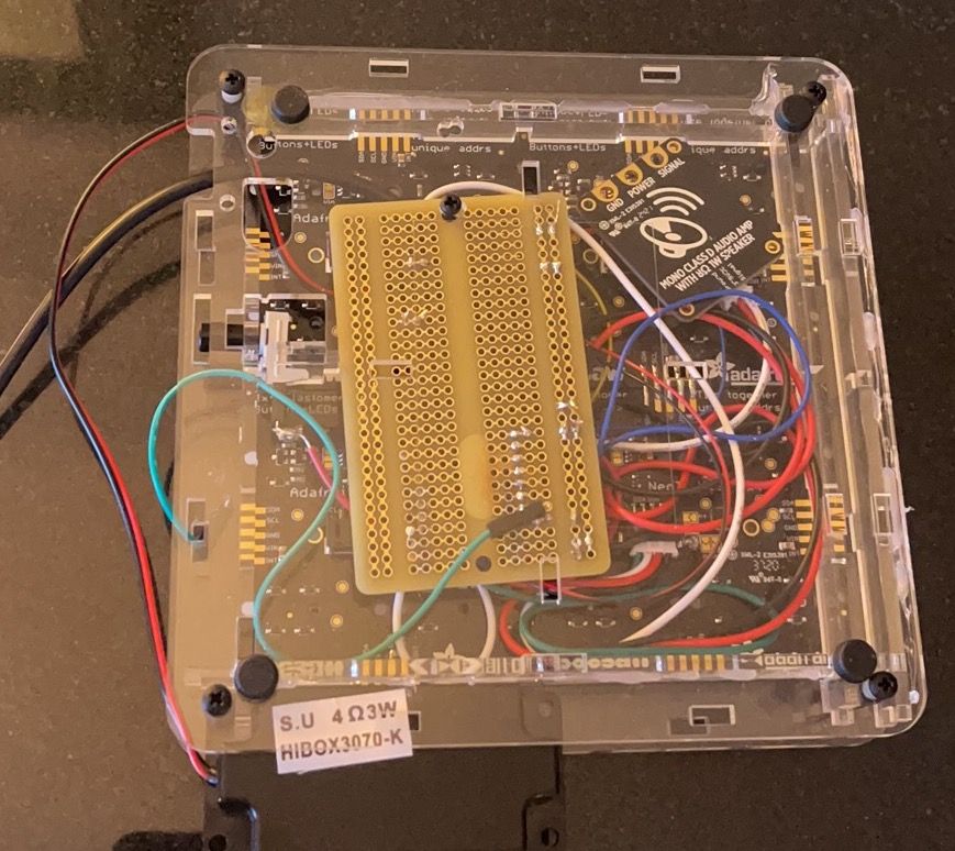
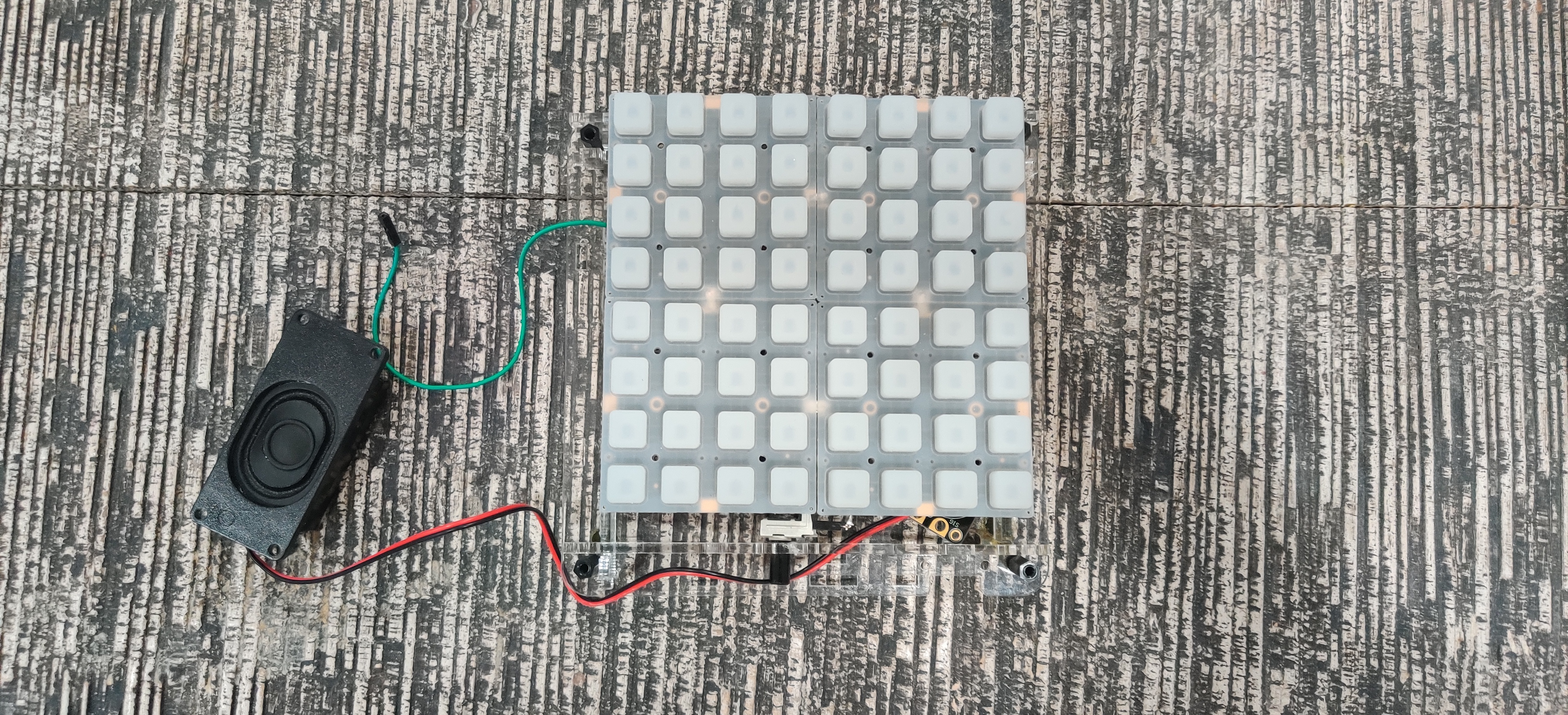
The soldered circuit is shown below:
Software
This program is mainly written with C and circuitpython, where C is controlling the UART communication between the PICO4ML and qtpy rp2040 then displaying the related information on LCD screen, and the circuit python realized the functionality of the launchpad (receiving users’ pressing data and controlling speaker) which is loaded on the qtpy rp2040. The detailed explaination of code will be shown in the next section.
Development environment
Visual Studio Code Version: 1.74.2
Tested on: Thinkpad X1, Windows 10 Pro, Intel(R) Core(TM) i7-8650U CPU @ 1.90GHz 2.11 GHzMU circuitpython editor Version: 1.1.1
Tested on: DELL XPS13, Windows 10Soldering and case assambling
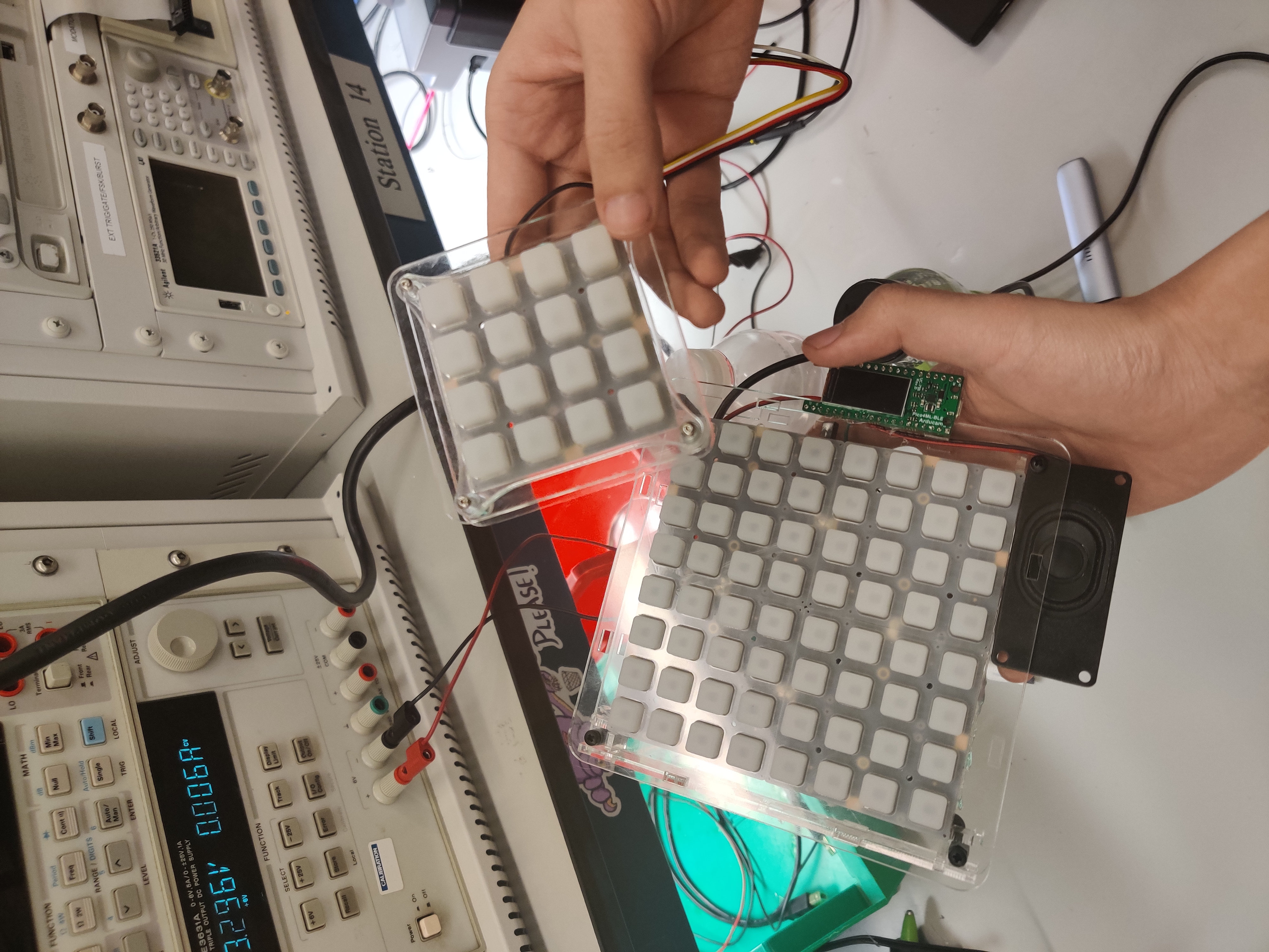
We assambed all component in
and we use four Neotrellis board
All components shown in circuit building section are placed at the back of adafruit Neotrellis case.
first, set the case:
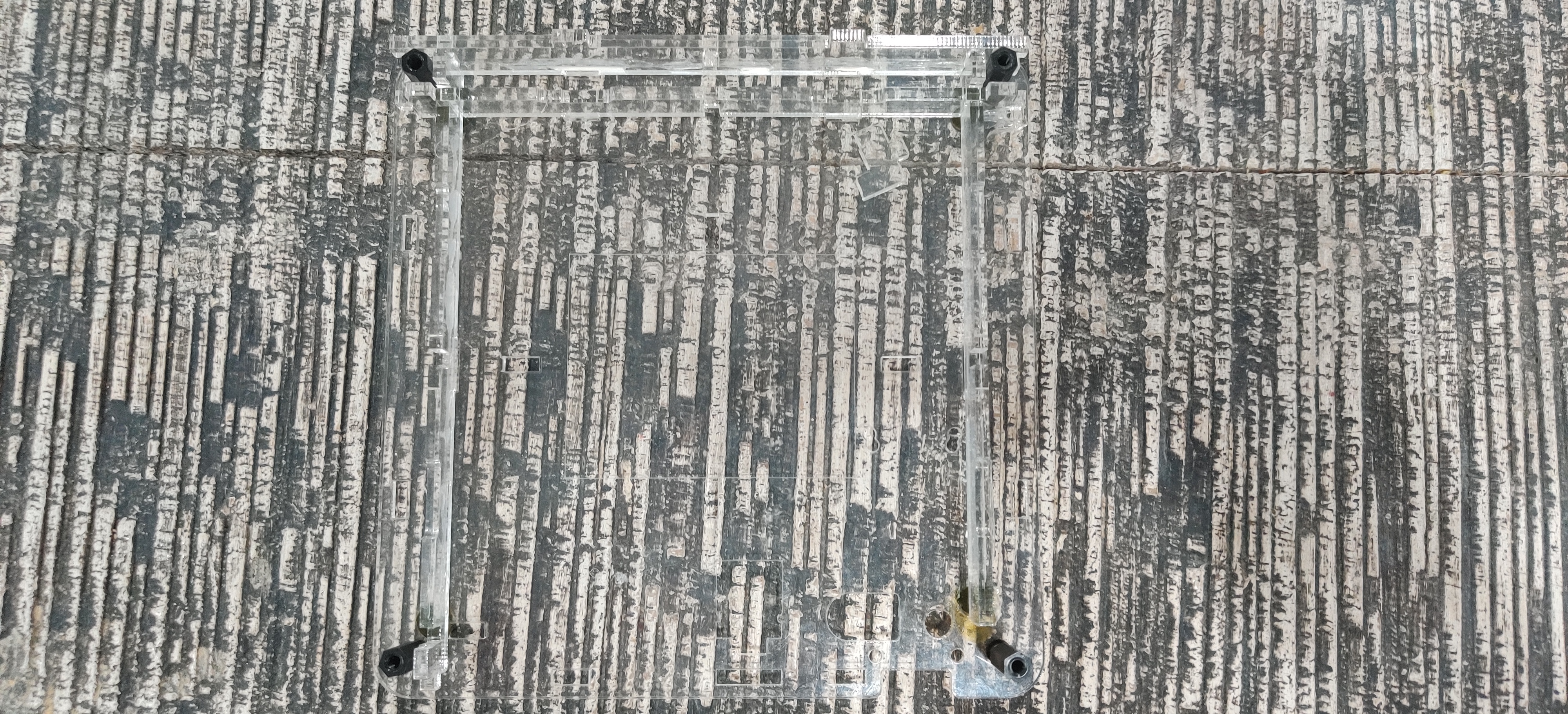
then put the variable resistor into the hole to make it a volumn controller
lastly, assemble the case and you are good to go
Low-pass filter assambling detail
Since we can only use the audiopwmio to drive the speaker, and we are using a audio amp for 8ohm 1w speaker, the speaker is easily overdrived,and the background noise is large. SO we need a low pass filter and voltage divider to solve the problem. For the voltage divider, we used a variable resistor to do the job, and for the low pass filter we use a 10 pf capacitor and a 1k ohm resistor which will wave out the sound above 5k hz,and we also use a 3.3uf capacitor to reduce the short circuit noise produce when the switcher is on and off.
Project development
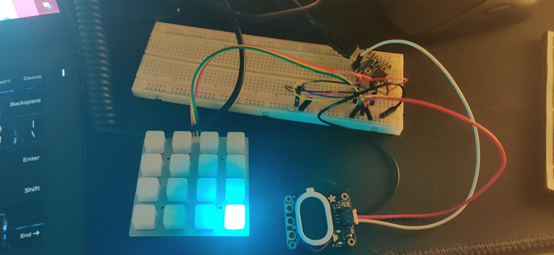
At first as we designed in proposal, we would like to design real time music game that will covert the analog sound signal to pitches and showing LED light on different pitches through FFT(Fast Fourier Transform). However, after talking with Professor Dalton, he recommanded us to use Adafruit Neotrellis to accomplish the goal,and we found a lot of interesting application on the Neotrellis,and we finally decided to make a real instrucment, a “launchpad”, instead of a music game hardware based machine. For the first stage of design ,we use a 4x4 Neotrellis board to make a Whack a Mole game on it
Stage 1 Whack a Mole
Stage1 demo is shown below:
https://youtu.be/9epRLCVayiY
The hole was randomly generated:
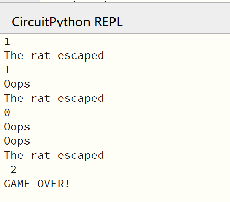
If you hit it in time, it will show no light, or you may hit wrong which shows red light, and the rat will escape after 0.5 second.
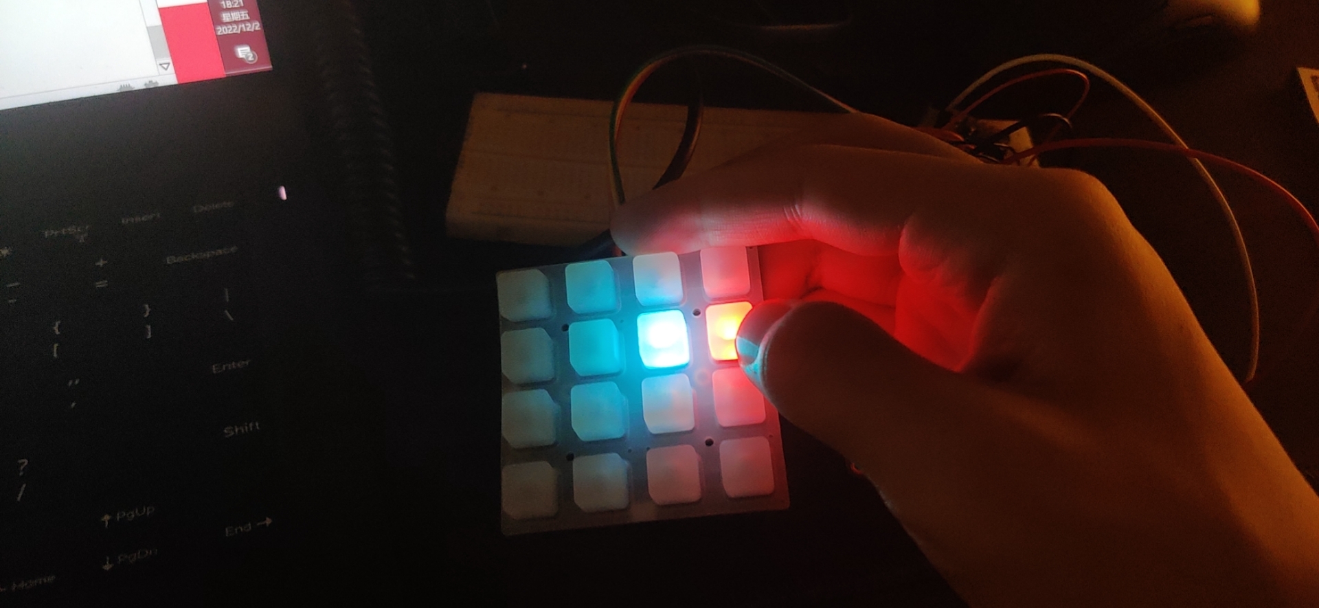
hit right gain +2, hit wrong gain -1, hit none gain 0 credits.
1591f55f30e0efb9959507cbaad0104
after you got below 0 score, game over!

Code
The code for the code for whack-a-mole mode is in first half of code.py.
Design
LCD on Pico4ML display:
We will show the credits on LCD screen which will read the data from RP2040 through PIO in/out. The “hello-world” code for LCD enable is shown here.
For LCD display, we basically use LCD_st7735.c with void ST7735_Init(void);, void ST7735_WriteString(uint16_t x, uint16_t y, const char *str, FontDef font, uint16_t color, uint16_t bgcolor); and void ST7735_FillScreen(uint16_t color); functions. The header file is shown below:
#ifndef __ST7735_H__
#define __ST7735_H__

#include "fonts.h"
#include <stdbool.h>

#define ST7735_MADCTL_MY 0x80
#define ST7735_MADCTL_MX 0x40
#define ST7735_MADCTL_MV 0x20
#define ST7735_MADCTL_ML 0x10
#define ST7735_MADCTL_RGB 0x00
#define ST7735_MADCTL_BGR 0x08
#define ST7735_MADCTL_MH 0x04
#define ST7735_RES_Pin GPIO_PIN_7
#define ST7735_RES_GPIO_Port GPIOC
#define ST7735_CS_Pin GPIO_PIN_6
#define ST7735_CS_GPIO_Port GPIOB
#define ST7735_DC_Pin GPIO_PIN_9
#define ST7735_DC_GPIO_Port GPIOA

// mini 160x80 display (it's unlikely you want the default orientation)

#define ST7735_IS_160X80 1
#define ST7735_XSTART 24
#define ST7735_YSTART 0
#define ST7735_WIDTH 80
#define ST7735_HEIGHT 160
//#define ST7735_ROTATION (ST7735_MADCTL_MX | ST7735_MADCTL_MY |
//ST7735_MADCTL_BGR)
#define ST7735_ROTATION (ST7735_MADCTL_BGR)

// mini 160x80, rotate left
/*
#define ST7735_IS_160X80 1
#define ST7735_XSTART 1
#define ST7735_YSTART 26
#define ST7735_WIDTH  160
#define ST7735_HEIGHT 80
#define ST7735_ROTATION (ST7735_MADCTL_MX | ST7735_MADCTL_MV |
ST7735_MADCTL_BGR)
*/

// mini 160x80, rotate right
/*
#define ST7735_IS_160X80 1
#define ST7735_XSTART 0
#define ST7735_YSTART 24
#define ST7735_WIDTH  160
#define ST7735_HEIGHT 80
#define ST7735_ROTATION (ST7735_MADCTL_MY | ST7735_MADCTL_MV |
ST7735_MADCTL_BGR)
*/
/****************************/

#define ST7735_NOP 0x00
#define ST7735_SWRESET 0x01
#define ST7735_RDDID 0x04
#define ST7735_RDDST 0x09

#define ST7735_SLPIN 0x10
#define ST7735_SLPOUT 0x11
#define ST7735_PTLON 0x12
#define ST7735_NORON 0x13

#define ST7735_INVOFF 0x20
#define ST7735_INVON 0x21
#define ST7735_DISPOFF 0x28
#define ST7735_DISPON 0x29
#define ST7735_CASET 0x2A
#define ST7735_RASET 0x2B
#define ST7735_RAMWR 0x2C
#define ST7735_RAMRD 0x2E

#define ST7735_PTLAR 0x30
#define ST7735_COLMOD 0x3A
#define ST7735_MADCTL 0x36

#define ST7735_FRMCTR1 0xB1
#define ST7735_FRMCTR2 0xB2
#define ST7735_FRMCTR3 0xB3
#define ST7735_INVCTR 0xB4
#define ST7735_DISSET5 0xB6

#define ST7735_PWCTR1 0xC0
#define ST7735_PWCTR2 0xC1
#define ST7735_PWCTR3 0xC2
#define ST7735_PWCTR4 0xC3
#define ST7735_PWCTR5 0xC4
#define ST7735_VMCTR1 0xC5

#define ST7735_RDID1 0xDA
#define ST7735_RDID2 0xDB
#define ST7735_RDID3 0xDC
#define ST7735_RDID4 0xDD

#define ST7735_PWCTR6 0xFC

#define ST7735_GMCTRP1 0xE0
#define ST7735_GMCTRN1 0xE1

// Color definitions
#define ST7735_BLACK 0x0000
#define ST7735_BLUE 0x001F
#define ST7735_RED 0xF800
#define ST7735_GREEN 0x07E0
#define ST7735_CYAN 0x07FF
#define ST7735_MAGENTA 0xF81F
#define ST7735_YELLOW 0xFFE0
#define ST7735_WHITE 0xFFFF
#define ST7735_COLOR565(r, g, b)                                               \
  (((r & 0xF8) << 8) | ((g & 0xFC) << 3) | ((b & 0xF8) >> 3))

#ifdef __cplusplus
extern "C" {
#endif
// call before initializing any SPI devices
void ST7735_Unselect();

void ST7735_Init(void);
void ST7735_DrawPixel(uint16_t x, uint16_t y, uint16_t color);
void ST7735_WriteString(uint16_t x, uint16_t y, const char *str, FontDef font,
                        uint16_t color, uint16_t bgcolor);
void ST7735_FillRectangle(uint16_t x, uint16_t y, uint16_t w, uint16_t h,
                          uint16_t color);
void ST7735_FillScreen(uint16_t color);
void ST7735_DrawImage(uint16_t x, uint16_t y, uint16_t w, uint16_t h,
                      const uint8_t *data);
void ST7735_InvertColors(bool invert);

#ifdef __cplusplus
}
#endif

#endif // __ST7735_H_
Firstly, before we want any display on LCD, void ST7735_Init(void); is used to initialize the screen. void ST7735_WriteString(uint16_t x, uint16_t y, const char *str, FontDef font, uint16_t color, uint16_t bgcolor) is used to write strings on LCD. We can easily display the strings char *str and define the strings’ location by setting uint16_t x and uint16_t y. Also, the strings’ color and the screen’s background color could be defined by uint16_t color and uint16_t bgcolor. Since the LCD could not actually “delate” previous strings, we can use void ST7735_FillScreen(uint16_t color); function to erase the previous display.
Also, fonts.c file has defined letters and symbols with different sizes: Font7x10[] and Font11x18[], each number represents the pixel in x and y each letter occupies. The header file is shown below:
/* vim: set ai et ts=4 sw=4: */
#ifndef __FONTS_H__
#define __FONTS_H__

#include <stdint.h>

typedef struct {
  const uint8_t width;
  uint8_t height;
  const uint16_t *data;
} FontDef;

extern FontDef Font_7x10;
extern FontDef Font_11x18;
extern FontDef Font_16x26;
extern const uint8_t arducam_logo[25608];
extern const uint16_t IMU_ICM20948[3200];

#endif // __FONTS_H__
Later, we will use the LCD display to give users relative information and display the patterns in the 4 steps drumer. The connection between Pico4ML with LCD and QT PY 2040 is needed.
Troubleshooting
- We use the neotrellis_simpletest.py Since the cable is not available, we solder the cable with copper pins.
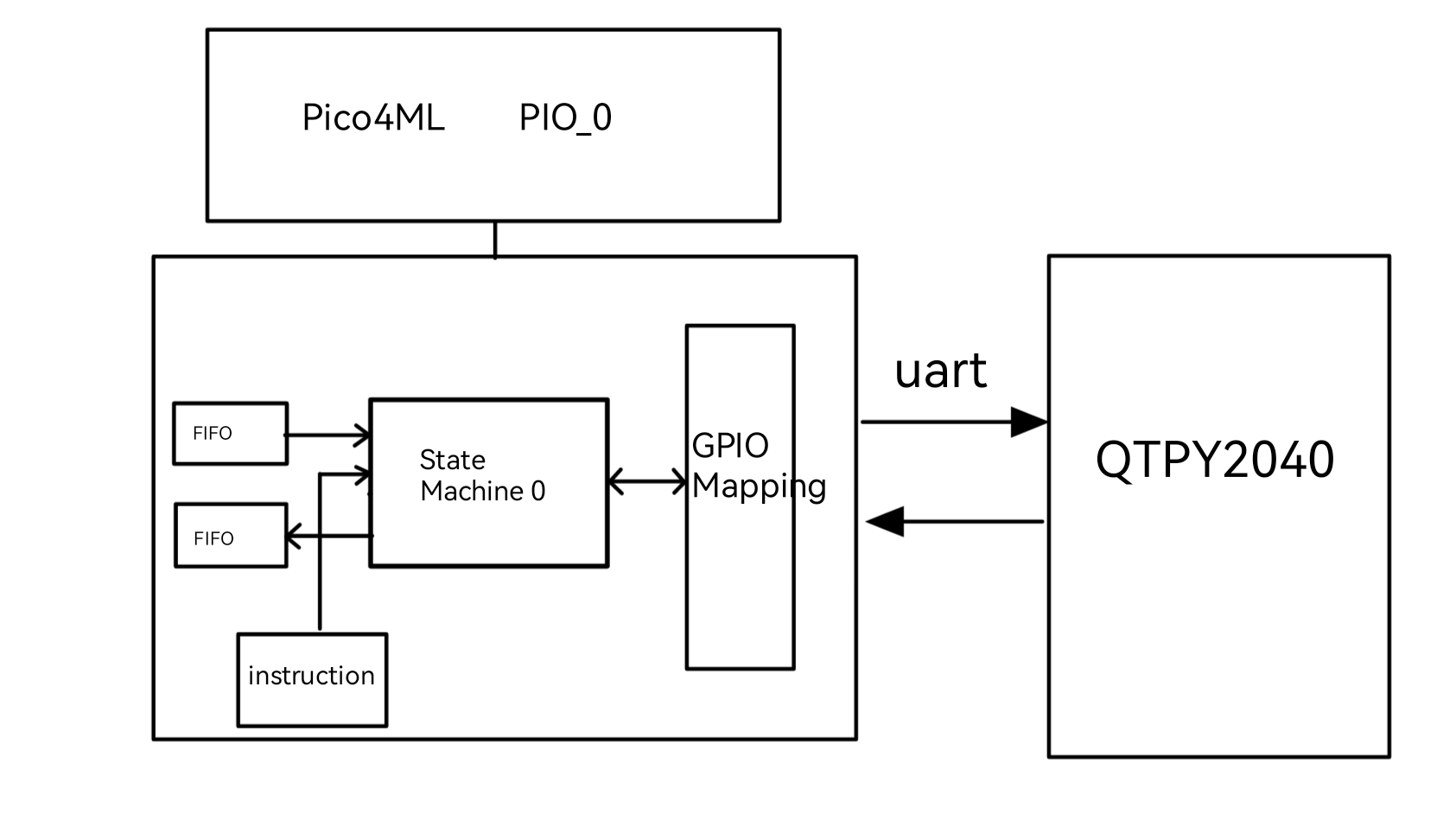
- Inspired by anothering group in demo day, we figured out that Pico4ML with LCD display could be connected with QT PY 2040 with UART with Tx/RX port. The basic logic is: when QT PY 2040 receive the users action, it can transport data to Pico4ML by TX writing port. By receiving data from RX port, Pico4ML could display some information on LCD screen with the library/code explained above. The design and system diagram is shown below: We can use uart with/without pio. The code we edited is shown here. We finally used PIO module in UART communication in our outlast design. In final design, QT PY 2040 will send data to Pico4ML when users select a specific mode, launchpad mode or sequencer mode, and the related information will be displayed on Pico4ML LCD. UART communication is also impleted in sequencer mode. The detailed explaination will be shown in Stage 3.
Stage 2 4-step drumer
Stage 2 demo is shown below:
https://youtu.be/yeAbvyMj_us
The 4 steps sequencer:
we use 4/4 time signature.
The drums are assigned with different color, and each button on y axis represents a quarter of a period. You can produce different combination of drums by pressing down those drum button and create drum beats.
Code
The code for the code for 4-step drumer mode is in second half of code.py.
Trouble shooting:
- the original code we used have the audioio module which didn’t implement on qtpy2040, so we use audiopwmio instead and it has a lower resolution of audio out.
Stage 3 8x8 8-Step drumer
After we get used to Neotrellis 4x4, we decided to solider four board to make it a 8x8 board, and we will realize a 8 step drumer on that with sample plaing. ### code
        for v in range(4):
            uart.write(bytes([BIT1[v]]))
            trellis.color(0,v,DRUM_COLOR[v])
            wave_file = open(DRUM[v], "rb")
            # OK we managed to open the wave OK
            for x in range(1,4):
                trellis.color(x,v,DRUM_COLOR[v])
            sample = audiocore.WaveFile(wave_file)
            # debug play back on load!
            mixer.play(sample, voice=0)
            for x in range(4, 8):
                trellis.color(x, v,DRUM_COLOR[v])
            while mixer.playing:
                pass
            #trellis.color(7,v,DRUM_COLOR[v])

            time.sleep(0.3)
            samples.append(sample)
Read the 4 wave files, convert to stereo samples, and store (show load status on neopixels and play audio once loaded too!)
define the global state
current_step = 7 # we actually start on the last step since we increment firstdefine the state of the sequencer
        beatset = [[False] * 8, [False] * 8, [False] * 8, [False] * 8]

        while A:

            stamp = time.monotonic()

            # redraw the last step to remove the ticker bar (e.g. 'normal' view)
            for y in range(4):
                color = 0
                if beatset[y][current_step]:
                    color = DRUM_COLOR[y]
                trellis.color(current_step,y,color)

            # next beat!
            current_step = (current_step + 1) % 8

            # draw the vertical ticker bar, with selected voices highlighted
            for y in range(4):
                if beatset[y][current_step]:
                    uart.write(bytes([BIT[y]]))
                    uart.write(bytes([Num[current_step]]))
                    r, g, b = DRUM_COLOR[y]
                    color = (r//2, g//2, b//2)  # this voice is enabled
                    mixer.play(samples[y], voice=y)
                    mixer.play(samples[y], voice=y)
                else:
                    color = TICKER_COLOR    # no voice on
                    #uart.write(bytes([0x45]))
                trellis.color(current_step,y, color)
            if current_step == 7:
                time.sleep(0.1)
                uart.write(bytes([0x45]))


            # handle button presses while we're waiting for the next tempo beat
            while time.monotonic() - stamp < 60/tempo:
                # Check for pressed buttons
                trellis.color(0,4,GOLD)

                trellis.sync()

                time.sleep(0.02)
we will use the blink function to check the pressed buttons.
            def blink(xo,yo,edge):
                if yo in range(4):
                    if edge == NeoTrellis.EDGE_RISING
                        beatset[yo][xo] = not beatset[yo][xo] # enable the voice
                        if beatset[yo][xo]:
                            color = DRUM_COLOR[yo]
                        else:
                            color = 0
                        trellis.color(xo,yo,color)
if the a rising edge is detected for the button, the beatset voice is now enbabled for that voice , and the color of that beat set is shown on the sequencer, else when you pressed again, the beatset voice is disabled, and the color is cleared.
                if xo == 0 and yo == 4:
                        if edge == NeoTrellis.EDGE_RISING:
                            data = open(ALONE1[0], "rb")
                            wav = audiocore.WaveFile(data)
                            mixer.voice[4].play(wav)
                            trellis.color(xo,yo,CYAN)
Also, we set the sample to play at the fifth channel of the mixer to not interupt with drum beat playing on the other channel
Touble shooting
In the original code, to make the drums to play at the same time, we use a mixer to play music in different channels. However, the sound samples in mixer are strictly required which means we may not use the sound files which is in different format, so we can only use the 16bit 2 channel 21600 sample rate WAV files instead of a MP3 files which we used in launchpad mode.
Stage 4 8x8 Launchpad with color functions
    A = False
    B = False

    IN = input("Sequencer: 1 ; Launchpad : 2  ;  1 or 2 ?:")
    if int(IN) == 1:
        uart.write(bytes([0x53]))
        for y in range(8):
            for x in range(8):
                trellis.set_callback(x,y,blink)
        A = True
    elif int(IN) == 2:
        uart.write(bytes([0x4c]))
        for y in range(8):
            for x in range(8):
                trellis.set_callback(x,y,blink2)
        B = True
To make the user to choose which mode they would like to play, we use a simple python input to realize that function. In this way, the user could choose the mode they want to play by interacting with console.
Then we made a number of light function which will produce different light effect when the button is pressed:
def cross(x,y,color):
    trellis.color(x,y,color)
    trellis.color(x,y,OFF)
    if x == 0 :
        if y == 0:
            trellis.color(x,y+1,color)
            trellis.color(x+1,y,color)
            trellis.color(x,y+1,OFF)
            trellis.color(x+1,y,OFF)
        elif y == 7:
            trellis.color(x,y-1,color)
            trellis.color(x+1,y,color)
            trellis.color(x,y-1,OFF)
            trellis.color(x+1,y,OFF)
        elif y in range(1,7):
            trellis.color(x,y+1,color)
            trellis.color(x,y-1,color)
            trellis.color(x+1,y,color)
            trellis.color(x,y+1,OFF)
            trellis.color(x,y-1,OFF)
            trellis.color(x+1,y,OFF)
    elif x == 7:
        if y == 0:
            trellis.color(x,y+1,color)
            trellis.color(x-1,y,color)
            trellis.color(x,y+1,OFF)
            trellis.color(x-1,y,OFF)
        elif y == 7:
            trellis.color(x,y-1,color)
            trellis.color(x-1,y,color)
            trellis.color(x,y-1,OFF)
            trellis.color(x-1,y,OFF)
        elif y in range(1,7):
            trellis.color(x,y+1,color)
            trellis.color(x,y-1,color)
            trellis.color(x-1,y,color)
            trellis.color(x,y+1,OFF)
            trellis.color(x,y-1,OFF)
            trellis.color(x-1,y,OFF)

    elif y == 0 and x in range(1,7):
        trellis.color(x,y+1,color)
        trellis.color(x+1,y,color)
        trellis.color(x-1,y,color)
        trellis.color(x,y+1,OFF)
        trellis.color(x+1,y,OFF)
        trellis.color(x-1,y,OFF)
    elif y == 7 and x in range(1,7):
        trellis.color(x,y-1,color)
        trellis.color(x+1,y,color)
        trellis.color(x-1,y,color)
        trellis.color(x,y-1,OFF)
        trellis.color(x+1,y,OFF)
        trellis.color(x-1,y,OFF)

    else:
        trellis.color(x,y+1,color)
        trellis.color(x,y-1,color)
        trellis.color(x+1,y,color)
        trellis.color(x-1,y,color)
        trellis.color(x,y+1,OFF)
        trellis.color(x,y-1,OFF)
        trellis.color(x+1,y,OFF)
        trellis.color(x-1,y,OFF)
def rainbow(x,y,color):
    for a in range(8):
        trellis.color(a,a,colorwheel(4*a*a))
        trellis.color(a,7-a,colorwheel(4*a*a))
    for a in range(8):
        trellis.color(a,a,OFF)
        trellis.color(a,7-a,OFF)

def block(x,y,color):
    if x in range(4) and y in range(4):
        for x in range(4):
            for y in range(4):
                trellis.color(x,y,colorwheel(4*x*y))
    if x in range(4,8) and y in range(4):
        for x in range(4,8):
            for y in range(4):
                trellis.color(x,y,colorwheel(4*x*y))
    if x in range(4) and y in range(4,8):
        for x in range(4):
            for y in range(4,8):
                trellis.color(x,y,colorwheel(4*x*y))
    if x in range(4,8) and y in range(4,8):
        for x in range(4,8):
            for y in range(4,8):
                trellis.color(x,y,colorwheel(4*x*y))

    for y in range(8):
        for x in range(8):
            trellis.color(x,y,OFF)
def waterx(x,y,color):
    for x in range(8):
        trellis.color(x,0,color)
        trellis.color(x,1,color)
        trellis.color(x,2,color)
        trellis.color(x,3,color)
        trellis.color(x,4,color)
        trellis.color(x,5,color)
        trellis.color(x,6,color)
        trellis.color(x,7,color)

    for x in range(7,-1,-1):
        trellis.color(x,0,OFF)
        trellis.color(x,1,OFF)
        trellis.color(x,2,OFF)
        trellis.color(x,3,OFF)
        trellis.color(x,4,OFF)
        trellis.color(x,5,OFF)
        trellis.color(x,6,OFF)
        trellis.color(x,7,OFF)

def watery(x,y,color):
    for y in range(8):
        trellis.color(0,y,color)
        trellis.color(1,y,color)
        trellis.color(2,y,color)
        trellis.color(3,y,color)
        trellis.color(4,y,color)
        trellis.color(5,y,color)
        trellis.color(6,y,color)
        trellis.color(7,y,color)

    for y in range(7,-1,-1):
        trellis.color(0,y,OFF)
        trellis.color(1,y,OFF)
        trellis.color(2,y,OFF)
        trellis.color(3,y,OFF)
        trellis.color(4,y,OFF)
        trellis.color(5,y,OFF)
        trellis.color(6,y,OFF)
        trellis.color(7,y,OFF)
def bigcross(x,y,color):
    for a in range(8):
        trellis.color(x,a,color)


    for b in range(8):
        trellis.color(b,y,color)

    for a in range(8):
        trellis.color(x,a,OFF)


    for b in range(8):
        trellis.color(b,y,OFF)
def spin(x,y,color):
    a = 1
    b = 1
    while a <= 5:
        for i in range(a):
            if y < 0 or y > 7:
                break
            x = x+b
            if x >= 0 and x <= 7:
                trellis.color(x,y,color)
                trellis.color(x-b,y,OFF)

            else:
                x = x-b
                break
        for j in range(a):
            if x < 0 or x > 7:
                break
            y = y+b
            if y <= 7 and y >= 0:
                trellis.color(x,y,color)
                trellis.color(x,y-b,OFF)
            else:
                y = y-b
                break
        a += 1
        b *= -1
    trellis.color(x,y,OFF)

def love(x,y,color):
    a=0
    b=0
    trellis.color(0+a,2+b,color)
    trellis.color(0+a,3+b,color)
    trellis.color(1+a,0+b,color)
    trellis.color(2+a,0+b,color)
    trellis.color(3+a,1+b,color)
    trellis.color(4+a,0+b,color)
    trellis.color(5+a,0+b,color)
    trellis.color(6+a,1+b,color)
    trellis.color(6+a,2+b,color)
    trellis.color(6+a,3+b,color)
    trellis.color(1+a,4+b,color)
    trellis.color(2+a,5+b,color)
    trellis.color(3+a,6+b,color)
    trellis.color(4+a,5+b,color)
    trellis.color(5+a,4+b,color)
    trellis.color(0+a,1+b,color)
    time.sleep(0.5)
    trellis.color(0+a,2+b,OFF)
    trellis.color(0+a,3+b,OFF)
    trellis.color(1+a,0+b,OFF)
    trellis.color(2+a,0+b,OFF)
    trellis.color(3+a,1+b,OFF)
    trellis.color(4+a,0+b,OFF)
    trellis.color(5+a,0+b,OFF)
    trellis.color(6+a,1+b,OFF)
    trellis.color(6+a,2+b,OFF)
    trellis.color(6+a,3+b,OFF)
    trellis.color(1+a,4+b,OFF)
    trellis.color(2+a,5+b,OFF)
    trellis.color(3+a,6+b,OFF)
    trellis.color(4+a,5+b,OFF)
    trellis.color(5+a,4+b,OFF)
    trellis.color(0+a,1+b,OFF)
def loveloop(x,y):
    i=0
    while True:
        if i < 255:
            trellis.color(0,2,colorwheel(i))
            trellis.color(0,3,colorwheel(i))
            trellis.color(1,0,colorwheel(i))
            trellis.color(2,0,colorwheel(i))
            trellis.color(3,1,colorwheel(i))
            trellis.color(4,0,colorwheel(i))
            trellis.color(5,0,colorwheel(i))
            trellis.color(6,1,colorwheel(i))
            trellis.color(6,2,colorwheel(i))
            trellis.color(6,3,colorwheel(i))
            trellis.color(1,4,colorwheel(i))
            trellis.color(2,5,colorwheel(i))
            trellis.color(3,6,colorwheel(i))
            trellis.color(4,5,colorwheel(i))
            trellis.color(5,4,colorwheel(i))
            trellis.color(0,1,colorwheel(i))
            i += 1
        elif i == 255:
            while (i>0):
                trellis.color(0,2,colorwheel(i))
                trellis.color(0,3,colorwheel(i))
                trellis.color(1,0,colorwheel(i))
                trellis.color(2,0,colorwheel(i))
                trellis.color(3,1,colorwheel(i))
                trellis.color(4,0,colorwheel(i))
                trellis.color(5,0,colorwheel(i))
                trellis.color(6,1,colorwheel(i))
                trellis.color(6,2,colorwheel(i))
                trellis.color(6,3,colorwheel(i))
                trellis.color(1,4,colorwheel(i))
                trellis.color(2,5,colorwheel(i))
                trellis.color(3,6,colorwheel(i))
                trellis.color(4,5,colorwheel(i))
                trellis.color(5,4,colorwheel(i))
                trellis.color(0,1,colorwheel(i))
                i -= 1
end

def cloud(x,y,color):
    for y in range(8):
        for x in range(8):
            trellis.color(x,y,colorwheel(4*x*y))
    for y in range(8):
        for x in range(8):
            trellis.color(x,y,OFF)
def cloud_edit(x,y,color):
i = 32
if i < 64:
if x == 4 and y == 4:
    for b in range(y,y+4,1):
        for a in range(x,x+4,1):
            rinbowgrab = color
            #trellis.color(a,b-1,OFF)
            rinbowgrab = (rinbowgrab[0],rinbowgrab[1]+4*i,rinbowgrab[2]+8*i)
            trellis.color(a,b,rinbowgrab)
            i = i+1
    for b in range(y,y+4,1):
        for a in range(x,x+4,1):
            trellis.color(a,b,OFF)
if x == 3 and y == 3:
    for b in range(y,y-4,-1):
        for a in range(x,x-4,-1):
            rinbowgrab = color
            rinbowgrab = (rinbowgrab[0],rinbowgrab[1]+4*i,rinbowgrab[2]+8*i)
            trellis.color(a,b,rinbowgrab)
            i = i+1
    for b in range(y,y-4,-1):
        for a in range(x,x-4,-1):
            trellis.color(a,b,OFF)
if x == 3 and y == 4:
    for b in range(y,y+4,1):
        for a in range(x,x-4,-1):
            rinbowgrab = color
            rinbowgrab = (rinbowgrab[0],rinbowgrab[1]+4*i,rinbowgrab[2]+8*i)
            trellis.color(a,b,rinbowgrab)
    for b in range(y,y+4,1):
        for a in range(x,x-4,-1):
            trellis.color(a,b,OFF)
if x == 4 and y == 3:
    for b in range(y,y-4,-1):
        for a in range(x,x+4,1):
            rinbowgrab = color
            rinbowgrab = (rinbowgrab[0],rinbowgrab[1]+4*i,rinbowgrab[2]+8*i)
            trellis.color(a,b,rinbowgrab)
            i = i+1
    for b in range(y,y-4,-1):
        for a in range(x,x+4,1):
            trellis.color(a,b,OFF)
else:
    love(x,y,color)
Trouble shooting
During the light progarm testing, we found an issue that since the light function is playing with the music playing, the speed of music playing the the light show playing will be affected when they play together, and the user can not interact with the buttons when the light is playing. Our guess is that the I2C bus is taking too much data from the borad, and it has reach its limit transmitssion speed, so in order to speed up the I2C transmission speed, we change the I2C frequency from 0.1Mhz to 0.4Mhz, and it significantly increased the speed of light functions.
PIO used for UART communication
Introduction to the RP2040 PIO module
Programmable I/O (PIO) is a new piece of hardware developed for RP2040. Serial communication is the main focus of PIO. I2C, SPI, and UART are three prominent serial protocols that are often hardware supported by microcontrollers. The number and kinds of serial interfaces that can be used, though, are always constrained by this hardware support. By offering a highly flexible, programmable I/O peripheral that will handle the bit-banging and offer straightforward input and output FIFO queues to the microcontroller core, PIO seeks to overcome this issue. In short, it allows you to create new types of (or additional) hardware interfaces on your RP2040-based device
For the purpose of manipulating GPIOs and transferring data, there are two PIO blocks, each with four state machines, which can operate independently. PIO state machines, as opposed to a general-purpose processor, are highly specialized for IO with an emphasis on determinism, exact timing, and close integration with fixed-function hardware.
In our project, since it is highly delay sensitive,we want to reduce the impact of latency on results. So we used PIO_UART to replace the traditional UART protocol.
Development process
Stage 1
Firstly, we try to use PIO_UART to both send and write data on the same RP2040 board with TX and RX port connected together:
#include "pico/stdlib.h"
#include "hardware/pio.h"
#include "uart_tx.pio.h"
#include <stdio.h>
#include "uart_rx.pio.h"
#include "hardware/clocks.h"
#include "LCD_st7735.h"

// normally attachc UART0 to.
// const uint PIN_TX = 0;
// This is the same as the default UART baud rate on Pico
// const uint SERIAL_BAUD = 115200;
const uint SERIAL_BAUD = 115200;
// normally attach UART1 to.
// const uint PIN_RX = 1;
#define PIN_TX 0
#define PIN_RX 1


int main() {
    stdio_init_all();
    gpio_init(PIN_TX);
    gpio_set_function(PIN_TX, GPIO_FUNC_UART);
    uint offset1 = pio_add_program(pio0, &uart_tx_program);
    uart_tx_program_init(pio0, 0, offset1, PIN_TX, SERIAL_BAUD);
    uint offset2 = pio_add_program(pio1, &uart_rx_program);
    uart_rx_program_init(pio1, 0, offset2, PIN_RX, SERIAL_BAUD);
    char c;
    while (true) {
        uart_tx_program_puts(pio0, 0, "hello");
        sleep_ms(1000);
        char c[5];
        for(int i = 0; i < 5; i++){
            c[i] = uart_rx_program_getc(pio1, 0);
        }
        printf("test\n");
        printf("%s",c);
        printf("\n");

        printf("test\n");
     }
     return 0;
 }
Firstly we set the serial speed as 115200 and TX/RX pins with 0 and 1 // const uint SERIAL_BAUD = 115200; const uint SERIAL_BAUD = 115200; // normally attach UART1 to. // const uint PIN_RX = 1; #define PIN_TX 0 #define PIN_RX 1 For the uart_tx and uart_rx setup, we seperately use pio0 for tx and pio1 for rx with both state machine 0. We also set PIN_TX with GPIO UART function. stdio_init_all(); gpio_init(PIN_TX); gpio_set_function(PIN_TX, GPIO_FUNC_UART); uint offset1 = pio_add_program(pio0, &uart_tx_program); uart_tx_program_init(pio0, 0, offset1, PIN_TX, SERIAL_BAUD); uint offset2 = pio_add_program(pio1, &uart_rx_program); uart_rx_program_init(pio1, 0, offset2, PIN_RX, SERIAL_BAUD); For sending data, we can send a string with uart_tx_program_puts()function. The input could be a string. uart_tx_program_puts(pio0, 0, "hello"); Note: for rx reading data, the uart_rx_program_getc() function only reads one character at a time, hence when we are sending “hello” that is 5 characters, hence we need to put a for loop for reading like follows
char c[5];
       for(int i = 0; i < 5; i++){
           c[i] = uart_rx_program_getc(pio1, 0);
       }
       printf("test\n");
       printf("%s",c);
Stage 2
Then we tried to read the data sent from one RP2040 TX port with circuitpython control at second RP2040 board RX port: circuitpython code:
import busio
import board
import time

uart = busio.UART(board.TX, board.RX, baudrate=9600)

while True:
    uart.write(bytes([0x60]))
    print("test???????????????")
    time.sleep(2)
    uart.write(bytes([0x55]))
    print("test---------------")
    time.sleep(2)
After first RP2040 send byte input and second board read the data, the data will be print at both board. The demo is shown below:
From the result above, we found that with different speed, the delay does not matter. So PIO_UART is a good choice for delay reduction.
Trouble shooting: 1. Different from C language, uart.write() function only allows bytes input. But it does not really matter in our case since uart_rx_program_getc() function also only reads one character at a time. So in our final design, we make circuitpython board send a letter to C when we want the new LCD information display. Each byte input from circuitpython can be converted to a letter due to ASCII. 2. Important! Both board should connected to the same PC when UART is running. We firstly tried to connect two board to different PCs, and no output is printed in console.
Stage 3
Finally, we modify both python and c code to use PIO_UART in our project. Firstly, we use switching case in the main function to show which mode the user is in. 1. Game initial When the user initialize(turn on) the pad, it will send a letter ‘s’ to Pico4ML. After Pico4ML received the letter, it will in initialize mode
case 's':
                game_init();
                break;
The LCD will display adafruit symbol and “Lauch Pad Music Game” on the screen. With ‘1’ to ‘5’ sent to Pico4ML, phrase with different color will be shown on the screen.
void game_init(){
     ST7735_FillScreen(ST7735_BLACK);
     while (true){
        char c = uart_rx_program_getc(pio1,0);
        putchar(c);
        if (c == '1'){
            ST7735_WriteString(7, 20, "LAUNCH", Font_11x18, ST7735_BLACK, ST7735_CYAN);
        }
        else if (c == '2'){
            ST7735_WriteString(23, 45, "PAD", Font_11x18, ST7735_BLACK, ST7735_GREEN);
        }
        else if (c == '3'){
            ST7735_WriteString(12, 70, "MUSIC", Font_11x18, ST7735_BLACK, ST7735_YELLOW);
        }
        else if (c == '4'){
            ST7735_WriteString(12, 95, "GAME!", Font_11x18, ST7735_BLACK, ST7735_RED);
        }
        else if (c == '5'){
            ST7735_FillScreen(ST7735_GREEN);
            break;
        }
}- Sequencer mode When the user choose the sequencer mode, it will send a letter ‘S’ to Pico4ML. After Pico4ML received the letter, it will in sequencer mode and show “Drum Mode” on LCD. After 1s sleep, LCD will show four rows of “oooooooo” indicating that four drum are initialized and not played.
case 'S':
                ST7735_WriteString(18, 30, "Drum", Font_11x18, ST7735_BLACK, ST7735_GREEN);
                ST7735_WriteString(18, 60, "Mode", Font_11x18, ST7735_BLACK, ST7735_GREEN);
                sleep_ms(1000);
                ST7735_FillScreen(ST7735_GREEN);
                char drum_1[9] = "oooooooo";
                char drum_2[9] = "oooooooo";
                char drum_3[9] = "oooooooo";
                char drum_4[9] = "oooooooo";

                // for (int j = 1; j < 5; j++){
                // ST7735_WriteString(3,20*j,drum_1,Font_7x10,ST7735_BLACK, ST7735_GREEN);
                //     }
                ST7735_WriteString(3, 20, drum_1, Font_7x10, ST7735_BLACK, ST7735_GREEN);
                ST7735_WriteString(3, 40, drum_2, Font_7x10, ST7735_BLACK, ST7735_GREEN);
                ST7735_WriteString(3, 60, drum_3, Font_7x10, ST7735_BLACK, ST7735_GREEN);
                ST7735_WriteString(3, 80, drum_4, Font_7x10, ST7735_BLACK, ST7735_GREEN);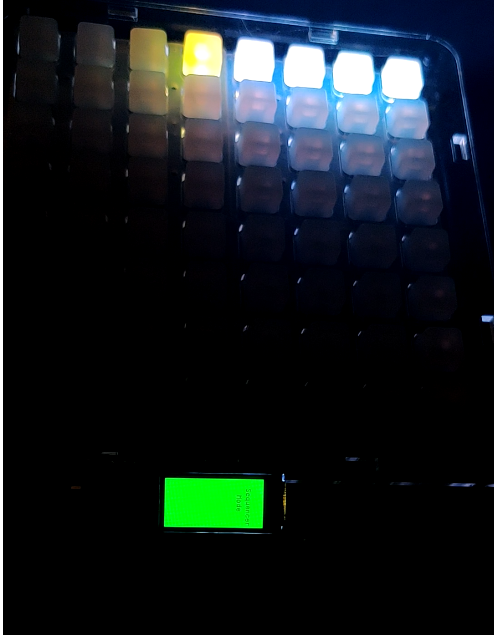
S_start_LCD
During the sequencer mode, QTPY2040 will continuous send data to Pico4ML:
        while (true){

            char drum = uart_rx_program_getc(pio1,0);

            if (drum == 'E'){
                for (int i = 0; i < 8; i++){
                    drum_1[i] = 'o';
                    drum_2[i] = 'o';
                    drum_3[i] = 'o';
                    drum_4[i] = 'o';
                }


               ST7735_FillScreen(ST7735_GREEN);
               ST7735_WriteString(3, 20, drum_1, Font_7x10, ST7735_BLACK, ST7735_GREEN);
               ST7735_WriteString(3, 40, drum_2, Font_7x10, ST7735_BLACK, ST7735_GREEN);
               ST7735_WriteString(3, 60, drum_3, Font_7x10, ST7735_BLACK, ST7735_GREEN);
               ST7735_WriteString(3, 80, drum_4, Font_7x10, ST7735_BLACK, ST7735_GREEN);
            }

            else if (drum == 'A'){
                char num = uart_rx_program_getc(pio1,0);
                int i = (int)(num) - 48;
                drum_1[i] = ' ';
                ST7735_WriteString(3, 20, drum_1, Font_7x10, ST7735_BLACK, ST7735_GREEN);
                ST7735_WriteString(3, 40, drum_2, Font_7x10, ST7735_BLACK, ST7735_GREEN);
                ST7735_WriteString(3, 60, drum_3, Font_7x10, ST7735_BLACK, ST7735_GREEN);
                ST7735_WriteString(3, 80, drum_4, Font_7x10, ST7735_BLACK, ST7735_GREEN);
                drum_1[i] = 'x';
                ST7735_WriteString(3, 20, drum_1, Font_7x10, ST7735_BLACK, ST7735_GREEN);
                ST7735_WriteString(3, 40, drum_2, Font_7x10, ST7735_BLACK, ST7735_GREEN);
                ST7735_WriteString(3, 60, drum_3, Font_7x10, ST7735_BLACK, ST7735_GREEN);
                ST7735_WriteString(3, 80, drum_4, Font_7x10, ST7735_BLACK, ST7735_GREEN);

            }
            else if (drum == 'B'){
                char num = uart_rx_program_getc(pio1,0);
                int i = (int)(num) - 48;
                drum_2[i] = ' ';
                ST7735_WriteString(3, 20, drum_1, Font_7x10, ST7735_BLACK, ST7735_GREEN);
                ST7735_WriteString(3, 40, drum_2, Font_7x10, ST7735_BLACK, ST7735_GREEN);
                ST7735_WriteString(3, 60, drum_3, Font_7x10, ST7735_BLACK, ST7735_GREEN);
                ST7735_WriteString(3, 80, drum_4, Font_7x10, ST7735_BLACK, ST7735_GREEN);
                drum_2[i] = 'x';
                ST7735_WriteString(3, 20, drum_1, Font_7x10, ST7735_BLACK, ST7735_GREEN);
                ST7735_WriteString(3, 40, drum_2, Font_7x10, ST7735_BLACK, ST7735_GREEN);
                ST7735_WriteString(3, 60, drum_3, Font_7x10, ST7735_BLACK, ST7735_GREEN);
                ST7735_WriteString(3, 80, drum_4, Font_7x10, ST7735_BLACK, ST7735_GREEN);

            }
            else if (drum == 'C'){
                char num = uart_rx_program_getc(pio1,0);
                int i = (int)(num) - 48;
                drum_3[i] = ' ';
                ST7735_WriteString(3, 20, drum_1, Font_7x10, ST7735_BLACK, ST7735_GREEN);
                ST7735_WriteString(3, 40, drum_2, Font_7x10, ST7735_BLACK, ST7735_GREEN);
                ST7735_WriteString(3, 60, drum_3, Font_7x10, ST7735_BLACK, ST7735_GREEN);
                ST7735_WriteString(3, 80, drum_4, Font_7x10, ST7735_BLACK, ST7735_GREEN);
                drum_3[i] = 'x';
                ST7735_WriteString(3, 20, drum_1, Font_7x10, ST7735_BLACK, ST7735_GREEN);
                ST7735_WriteString(3, 40, drum_2, Font_7x10, ST7735_BLACK, ST7735_GREEN);
                ST7735_WriteString(3, 60, drum_3, Font_7x10, ST7735_BLACK, ST7735_GREEN);
                ST7735_WriteString(3, 80, drum_4, Font_7x10, ST7735_BLACK, ST7735_GREEN);

            }
            else if (drum == 'D'){
                char num = uart_rx_program_getc(pio1,0);
                int i = (int)(num) - 48;
                drum_4[i] = ' ';
                ST7735_WriteString(3, 20, drum_1, Font_7x10, ST7735_BLACK, ST7735_GREEN);
                ST7735_WriteString(3, 40, drum_2, Font_7x10, ST7735_BLACK, ST7735_GREEN);
                ST7735_WriteString(3, 60, drum_3, Font_7x10, ST7735_BLACK, ST7735_GREEN);
                ST7735_WriteString(3, 80, drum_4, Font_7x10, ST7735_BLACK, ST7735_GREEN);
                drum_4[i] = 'x';
                ST7735_WriteString(3, 20, drum_1, Font_7x10, ST7735_BLACK, ST7735_GREEN);
                ST7735_WriteString(3, 40, drum_2, Font_7x10, ST7735_BLACK, ST7735_GREEN);
                ST7735_WriteString(3, 60, drum_3, Font_7x10, ST7735_BLACK, ST7735_GREEN);
                ST7735_WriteString(3, 80, drum_4, Font_7x10, ST7735_BLACK, ST7735_GREEN);

            }
            else if (drum == 'F'){
                ST7735_FillScreen(ST7735_GREEN);
                ST7735_WriteString(18, 30, "Mode", Font_11x18, ST7735_BLACK, ST7735_GREEN);
                ST7735_WriteString(18, 60, "Stopped", Font_11x18, ST7735_BLACK, ST7735_GREEN);
                break;
            }
- A-D indicates which instrument (which row) are playing during scanning. Then a number after the letter shows the instrument is playing in which meter. If there is a playing instrument, ‘o’ will be erase by ’ ’ and then display a ‘x’ at that place
- After a loop, ‘E’ will be sent to Pico4Ml and all o/x will be refresh to all o’s
- When the mode end, an ‘F’ will be sent to Pico4ML. Then the program
breakthe mode.
- Launchpad mode When the user choose , it will send a letter ‘s’ to Pico4ML. After Pico4ML received the letter, it will in Lauchpad mode.
case 'L':
                ST7735_WriteString(12, 30, "Music", Font_11x18, ST7735_BLACK, ST7735_GREEN);
                ST7735_WriteString(18, 60, "Mode", Font_11x18, ST7735_BLACK, ST7735_GREEN);
                sleep_ms(500);
                ST7735_WriteString(7, 90, "Enjoy!", Font_11x18, ST7735_RED, ST7735_GREEN);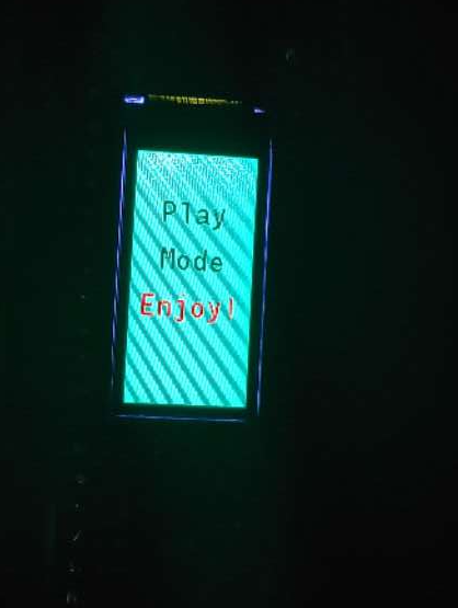
L_start_LCD
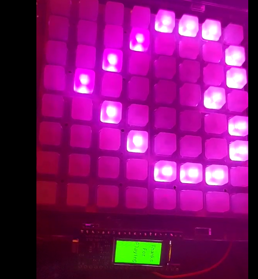
When the user press the last button on keypad, the mode will end and QTPY 2040 will send a letter ‘E’ to Pico4ML indicating there is an ending
char end = uart_rx_program_getc(pio1,0);
                if (end == 'E'){
                    ST7735_FillScreen(ST7735_GREEN);
                    ST7735_WriteString(7, 20, "Thanks", Font_11x18, ST7735_BLACK, ST7735_GREEN);
                    ST7735_WriteString(23, 50, "For", Font_11x18, ST7735_BLACK, ST7735_GREEN);
                    ST7735_WriteString(2, 80, "Playing", Font_11x18, ST7735_BLACK, ST7735_GREEN);
                    break;
                }
L_end_LCD
Final stage
We soldering the wire to one borad, and assamble them to the case.
Trouble shooting:
Since we can only use the audiopwmio to drive the speaker, and we are using a audio amp for 8ohm 1w speaker, the speaker is easily overdrived,and the background noise is large. SO we need a low pass filter and voltage divider to solve the problem. For the voltage divider, we used a variable resistor to do the job, and for the low pass filter we use a 10 pf capacitor and a 1k ohm resistor which will wave out the sound above 5k hz,and we also use a 3.3uf capacitor to reduce the short circuit noise produce when the switcher is on and off.
Reflections Pros/cons
RP204 pros:
circuit python, large storage, RT and TX supported for board commmunciation
cons:
uncomplished python libary which didnot include audioio to play audio, low default I2C frequency
PICO4ML:
Pros: LCD display
Cons: Small storage for data so we can not improve the quality of the music output by loading larger music files.
Neotrellis:
Pros: Easy to use and program, silicon button embedded with Neopixel LEDs
Cons: Since the Neopixel leds on the board can only be assesed one at a time with circuitpython, the delay of the LED light show is significant, and even more obvious when the audio is playing with the light functions.
4ohm 3w Speaker
Pros: sensitive and high quality sound supported,and easy to drive with the AMPs
Cons: Since we can only use the audiopwmio to drive the speaker, and we are using a audio amp for 8ohm 1w speaker, the speaker is easily overdrived,and the background noise is large. SO we need a low pass filter and voltage divider to solve the problem.
Future improvements:
We will use a SD card to store the music files, so that we can store a much larger sample file groups to directly used by the board. Also, we will update the library of the ciruitpython for the Neotrellis to make the Neopixel LED control easier and faster in a more pratical way. Next, we will update the audio output drive to use audioio instead of audiopwmio to produce a better sound output quality. Finally, we will add more functions to the sequencer such as a speed up and speed down moduel for each beat using time stamp and a recording cycle which will loop the notes you played with.
Feature accomplisments
One of the most interesting feature we have accomplished is the 8 step sequencer playing with the audio sample. Since for a real launchpad, the sample should go along withthe drum beat to produce a basic beat fot the music production,and we produce a 8 beat drum sample which could be real time modified and redistributed to syncronized samples that will give instant feedback to the music composer. It is really exiting to realize the function of producing a drum beat.
The second part which is really exciting is to make a LCD display based on URAT data transmission. By using PIO, the delay of the two board data transmisson is minized. Also, by using URAT to transport data, it will solve the problem that the I2C bus is loading too musch data at the same time, so it is very practical in the future study.